About TrackMaker
The best advantage of our software is unmatched ease of use. Unlike other softwares on the market, TrackMaker is designed for complete ease of use, meaning no prior CNC programming knowledge is needed. Users can start milling immediately without the steep learning curve associated with other systems. Intuitive user interface simplifies PCB preparation – Competitor software often requires complex manual adjustments, while TrackMaker automates the entire process.
Trackmaker allows direct import from KiCad, Eagle, and other EDA tools – unlike some competing software that requires additional conversion steps, TrackMaker allows smooth data import and easy Gerber/Excellon file processing.
Automatic milling strategy recommendation – competitor systems often require manual selection of milling parameters, whereas TrackMaker intelligently suggests the best milling method and tooling, saving time and reducing errors.
Automated tool change prompts – the software alerts the user when it's time to change tools, preventing mistakes and ensuring process continuity.
Guided double-sided PCB milling – TrackMaker provides clear instructions for flipping the board, eliminating common alignment errors found in competing solutions.
|
|
 |
 |
 |
 |
|
|
|
|
|
.png) |
.png) |
.png) |
.png) |
.png)
.png)
.png)
.png)
TrackMaker in general
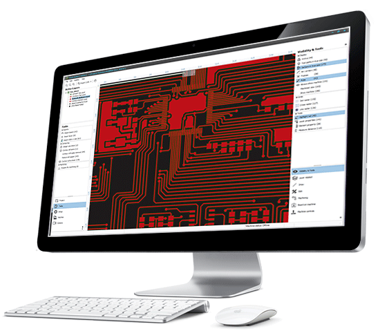
The purpose of this software is preparation and fabrication of printed circuit boards (PCB) on Mipec milling machines. Using data generated by the TrackMaker, the machine can perform following tasks:
- Mill along the contours of tracks, pads (footprints) and other conductive elements on a PCB layer in order to insulate connections from surrounding copper on the copper clad sheet of laminate
- Optionally remove copper in those areas on the PCB where there are no connections
- Drill holes
Source data for calculation and generation of tool paths are images of PCB layer artworks and drilling data imported from files created by various software packages for PCB layout design (CAD EDA software)
Source data for calculation and generation of tool paths are images of PCB layer artworks and drilling data imported from files created by various software packages for PCB layout design (CAD EDA software).
Most PCB CAD software packages export PCB layer images in so-called Gerber format that was primarily intended for rendering artworks on photo-plotters. However, this became the industry standard and is still used today. These images in their raw form are not suitable for passing directly to milling machines. They require processing through a complex contouring algorithm in order to calculate correct tool paths. By the term “tool paths”, we assume; lines that visually and mechanically insulate the elements of the board from the rest of the copper surface on a copper clad laminate once the machining has been done.
Drilling data is exported from PCB CAD packages in the format known as Excellon Program Format. In this case, the program needs only to convert drilling information to format acceptable by milling machine.
The procedure for PCB fabrication consists of following steps:
- Import of artworks images (Gerber files), separately for each PCB layer, or importing a complete folder providing that the layer mapping is known
- Import of PCB outlines (Gerber files)
- Import of drilling data (Excellon files); There is also a provision to reconstruct drilling data from selectively imported artwork elements in Gerber files
- Optional editing of imported data - it is sometimes necessary to edit the PCB outline and / or internal cutouts. Other important editing step at this stage may be aligning imported layers to the common origin
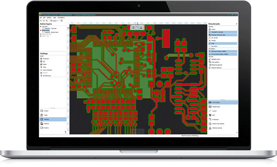
- Setting up fabrication and contouring parameters (contouring strategies, tool sizes, required DRC checks etc.)
- Defining areas where copper removal should take place (optional)
- Calculation of tool paths (contouring)
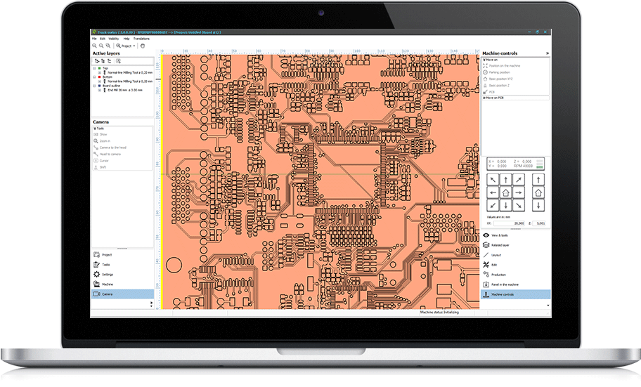
- Defining position of processed board on machine table
- Starting milling and drilling operations
The software provides also a set of advanced features that allow editing imported artwork images, drill templates and – as already mentioned board outline and cutouts. Tool paths - the contours generated by the program – may also be edited in cases where manual change (and eventual corrections) of automatically obtained results is required.
Editing commands enable the user to remove, relocate or transform graphical elements in artwork images, outlines and tool paths. Drilled holes may be removed and relocated. There are also functions for changing geometrical properties of elements - lengths, sizes, diameters and shapes. Commands for defining shapes and sizes of copper removal areas are also incorporated into editing commands set.
Apart from operating on imported elements, the user may manually add elements to artwork images and create new holes. At times, it is necessary to create board outlines and cutouts without importing. Commands for this task are also provided.
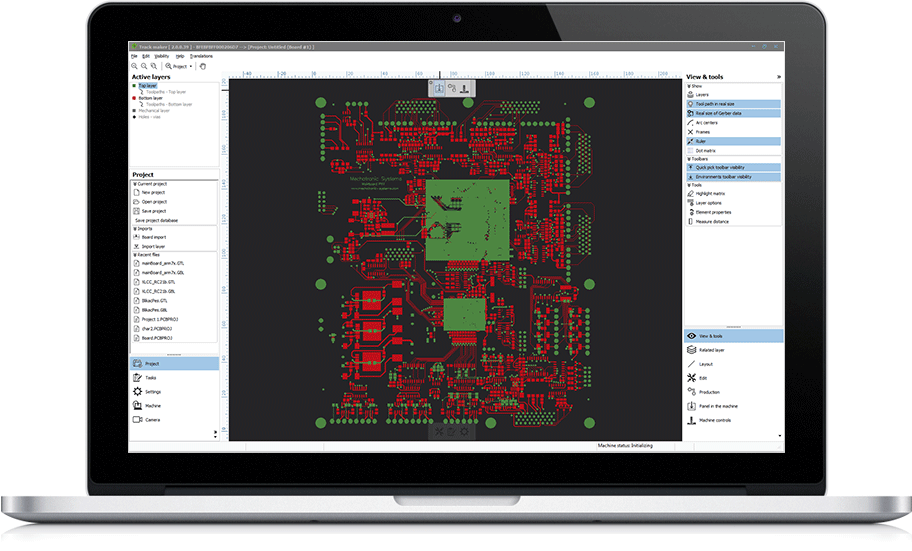
Graphical User Interface (GUI) of TrackMaker user interface provides a logical, readily accessible and customizable command grouping. Most of the commands are organized in tabs at each side of the workspace.
For example, on the left side of the screen you can find the layer navigator and in the tabs access to more general settings of project. On the right side are the tools that are used while working with the machine or with data.
The complete TrackMaker database may be stored in a single disc file called project. User can create as many projects as he wishes, save them and re-load them again. A project consists of at least one board. The term Board represents an entity consisting of multiple layers that form a PCB. For example, a project with double layer PCB consists of imported artworks for bottom and top layers, their calculated contours as well as well as drill and board outline layers. Project Database contains also milling representation of the layers.
TrackMaker GUI provides means for navigation through entities of the Project Database in form of Active layers panel. Active layer provides quick access to any Board in the database and its layers at preparation stage of processing. Access to milling sequence in actual fabrication stage is arranged in similar manner, by using the Tool Explorer which is seamlessly integrated into Active Layers.
Operation like loading projects, importing boards and layers, may be initiated by commands or simply by dragging files from Windows Explorer and dropping them over TrackMaker workspace.